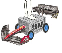
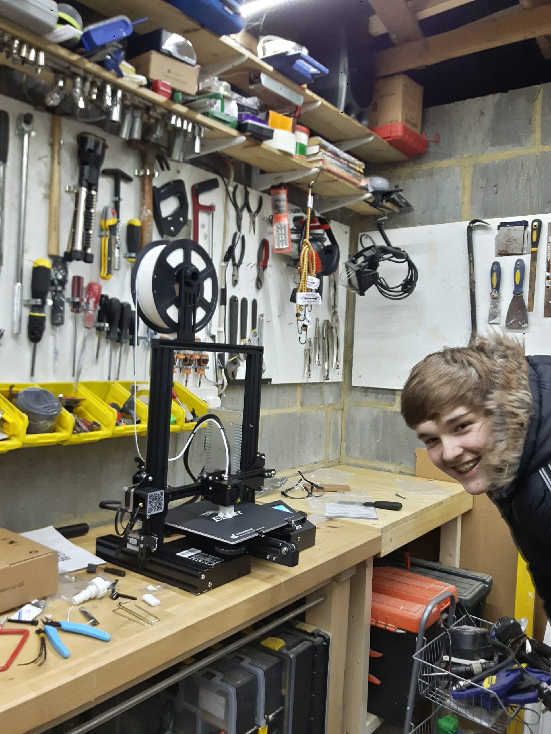
One of my first projects with my Ender 3 was perfectly timed with the middle of the LMP1 golden years of le Mans with Porsche winning the 2017 race with their 919 Hybrid. I figured if I’m going to all of the trouble of making my own wheel then I might as well make the best that year, so I did.
All of the files used in this was sourced from Thingiverse.
Original Files:
For this project I decided to print and make the following designs:
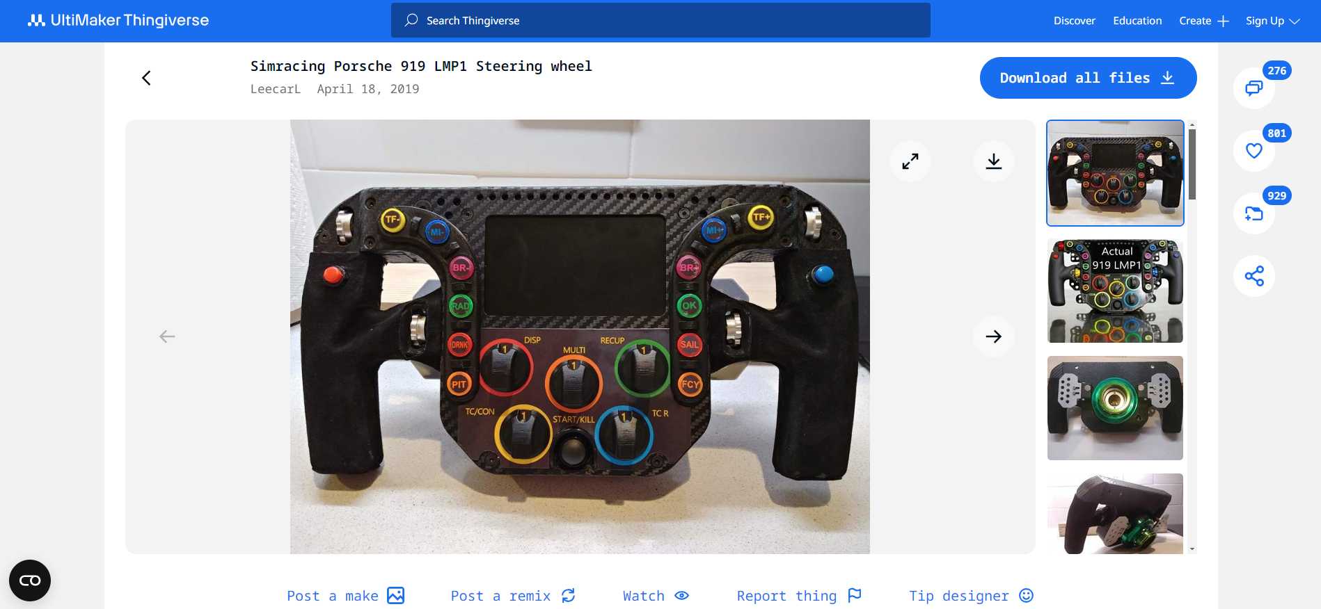
Porsche 919 Wheel by Leecarl,
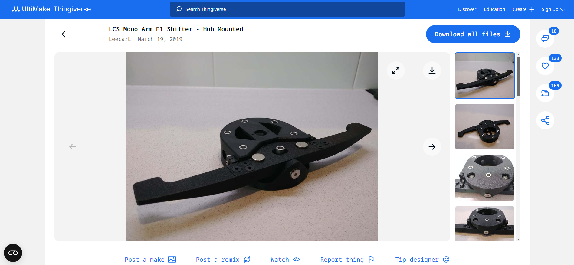
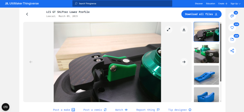
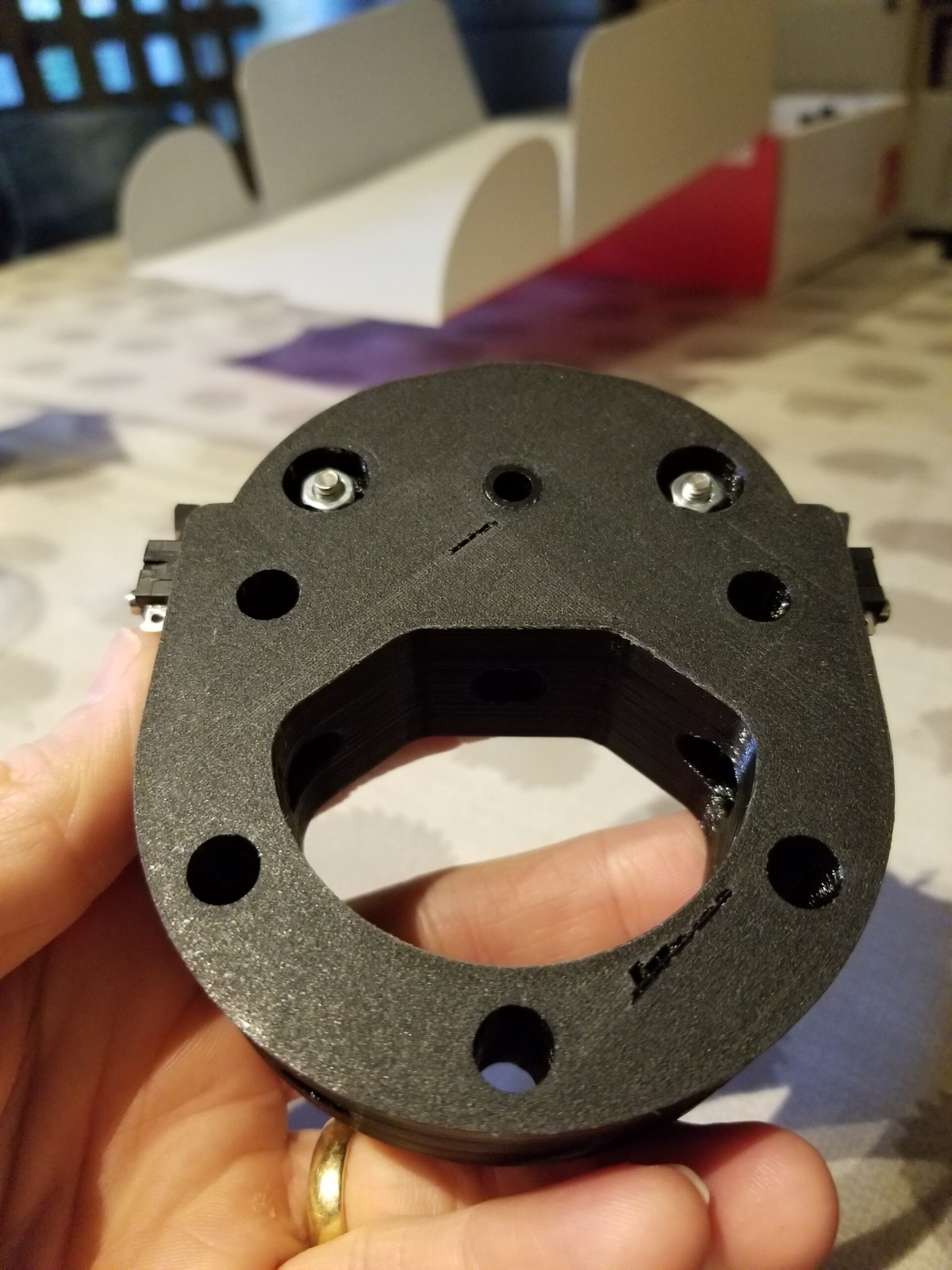
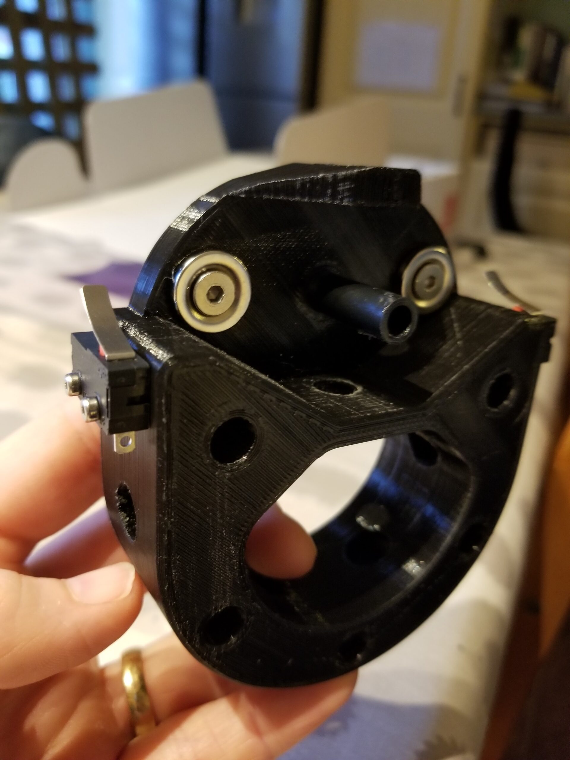
LCS Mono Arm F1 Shifter by Leecarl,
Thrustmaster Hub Adapter by Slowly.
by Leecarl
by Leecarl
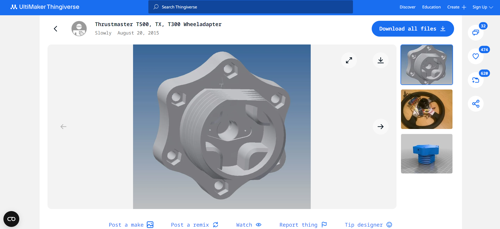
by Slowly
by Leecarl
Printing:
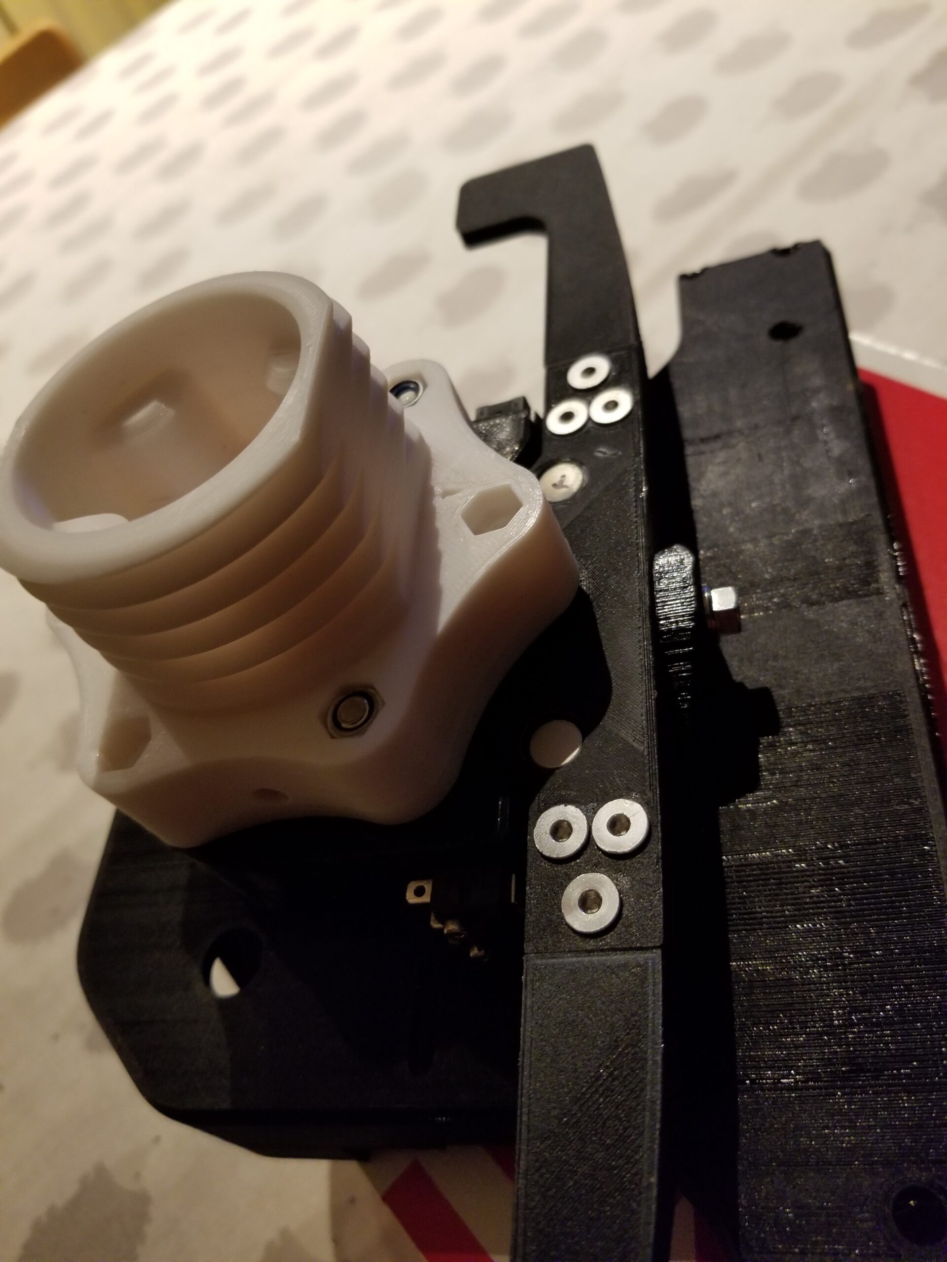
One of the first parts I printed was the hub adapter as it seems like the make or break component of the wheel so why not start there and work my way towards the front?
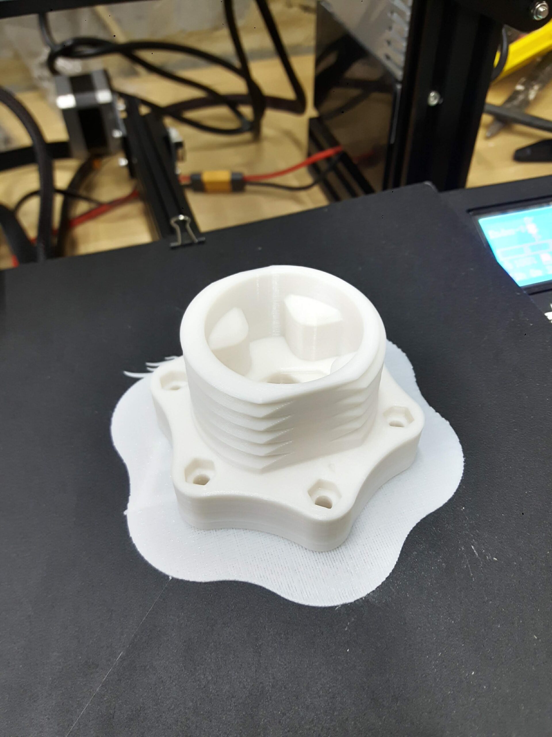
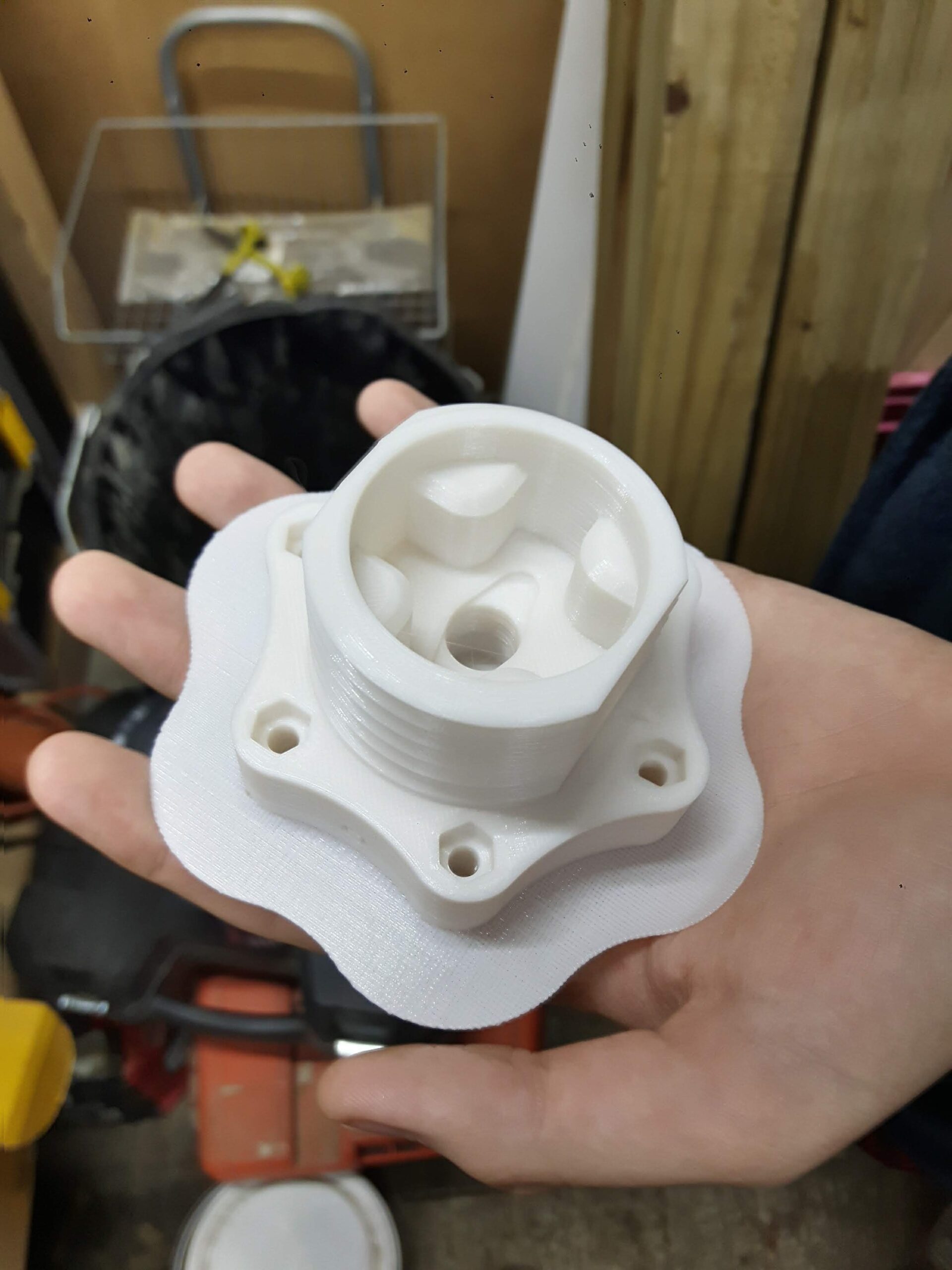
The hub fabrication went well for my first slice. I went for 0.15mm layer height as I thought the threads could probably do with being as smooth as possible and bumped up the infill to 50% for some added strength.
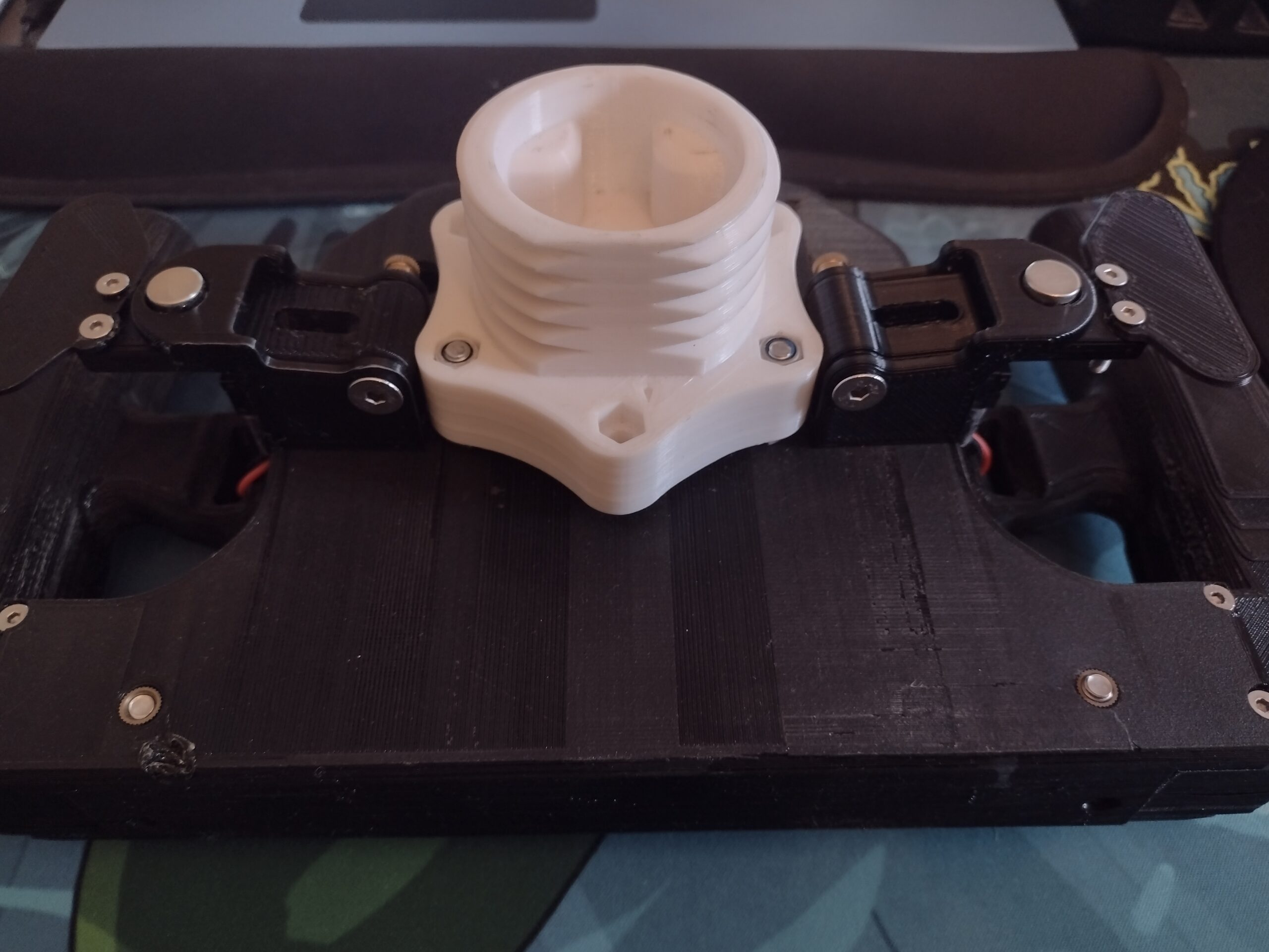
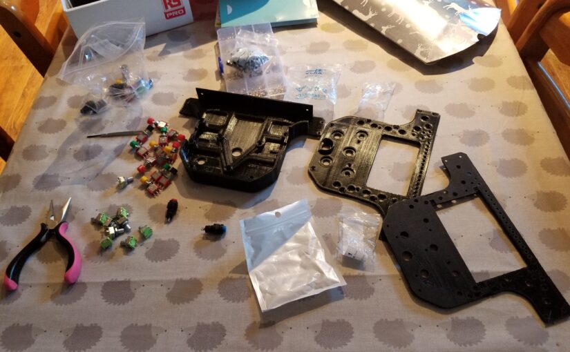
Next up was the shifters. After printing out the main hub I then inserted the nylon spacers in then attached the magnets and limit switches.
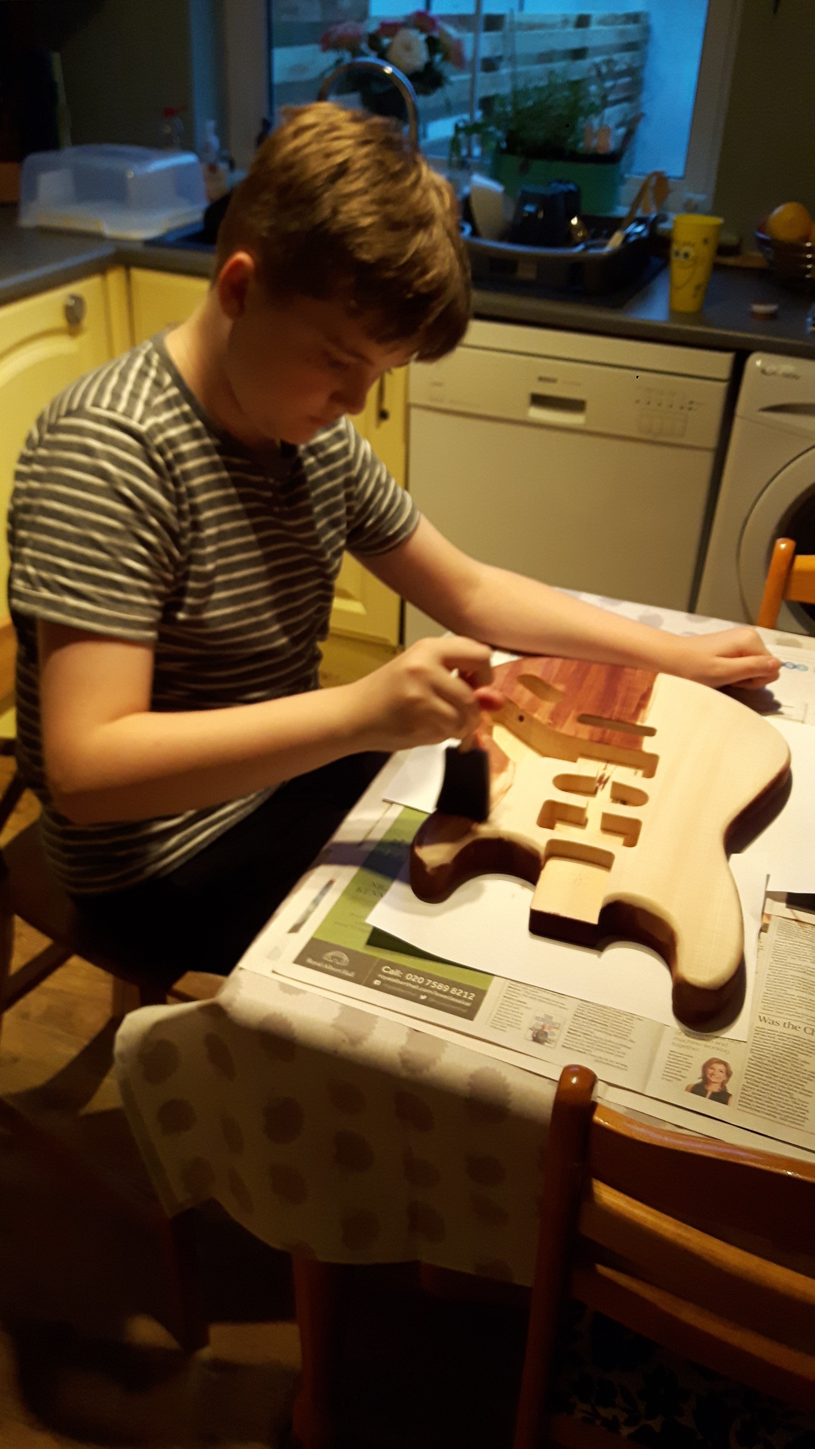
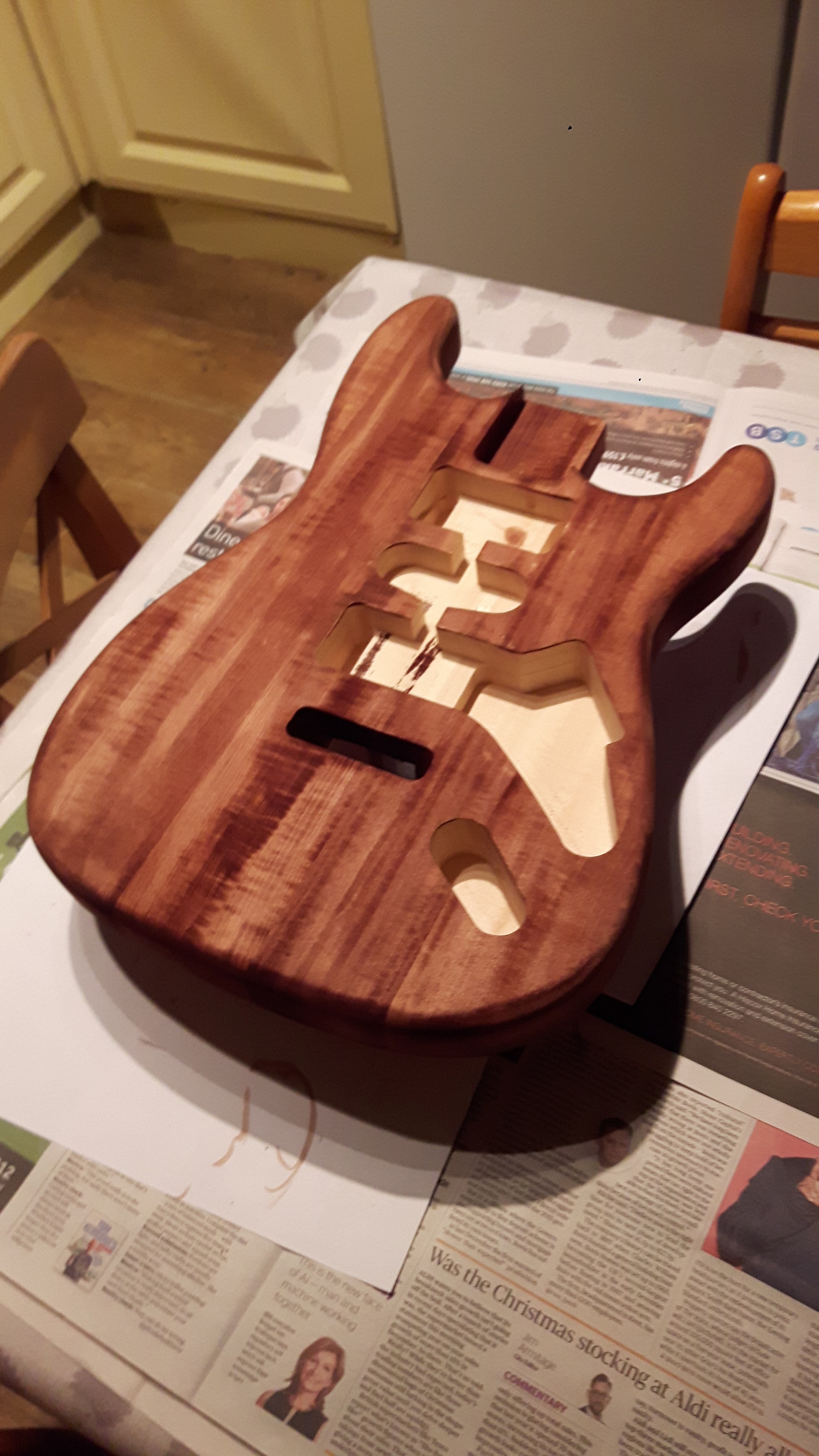
The last thing to print (initially) was the actual wheel itself. Printing went well overall and the design is very good, Leecarl’s instructions were very thorough although I decided against using rotary encoders and the screen as I accidentally melted all of the encoders and I normally play in VR.
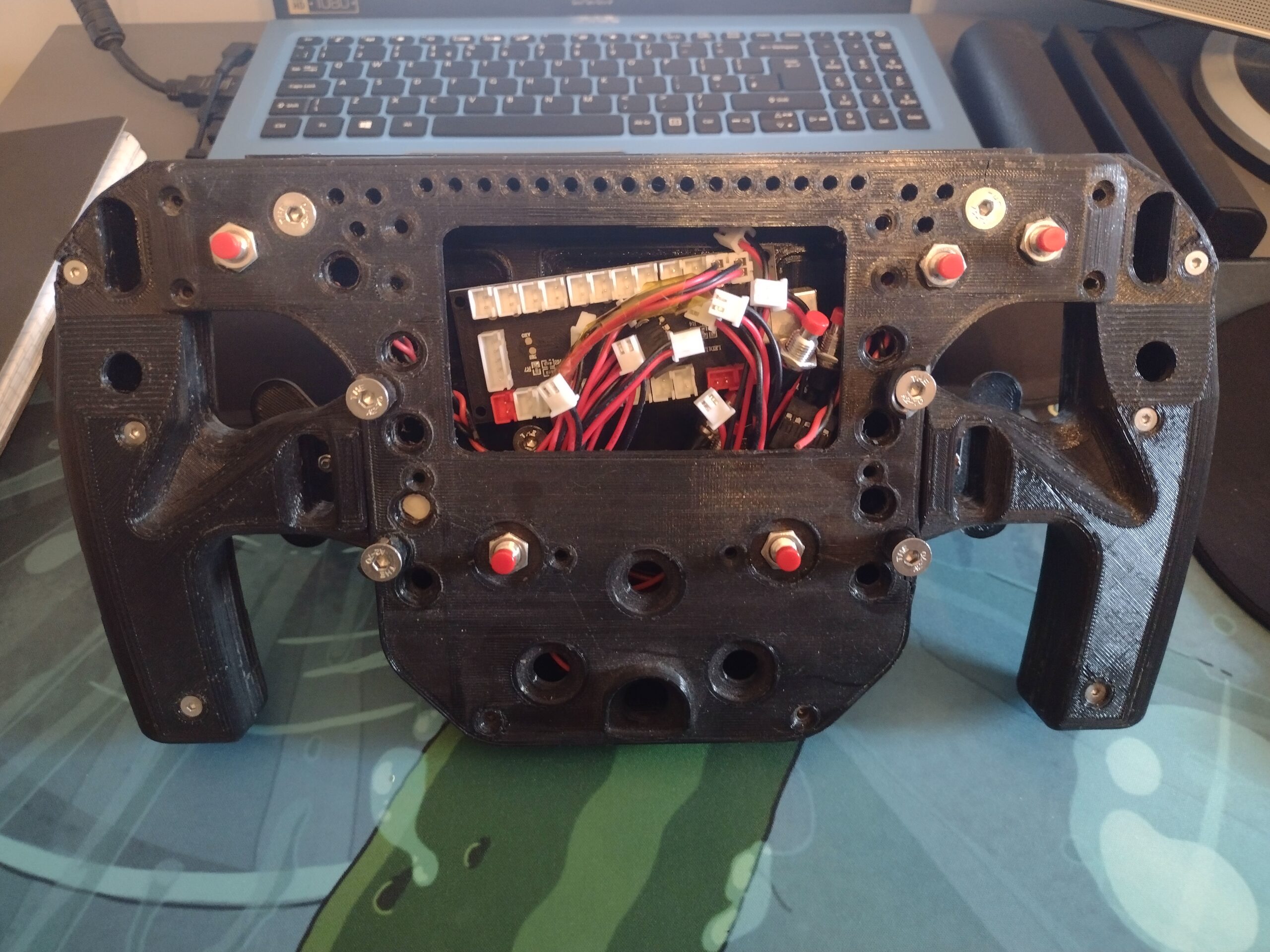
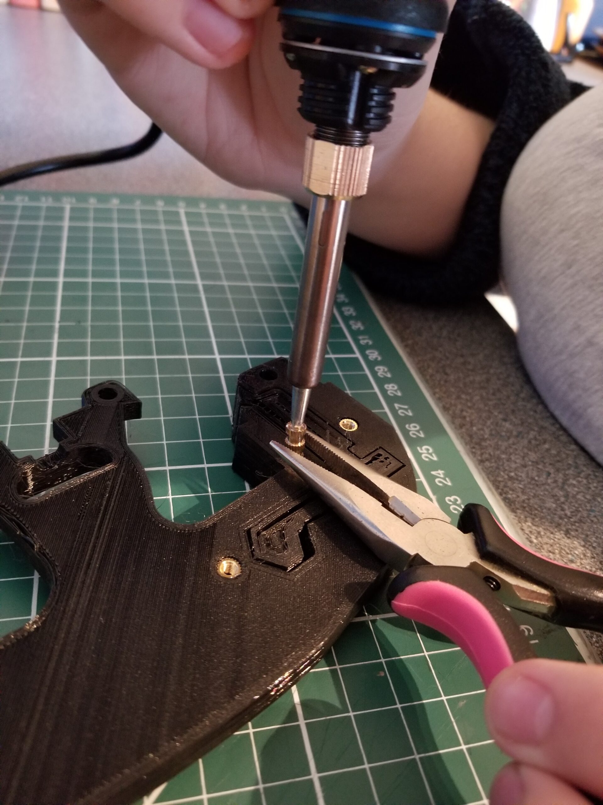
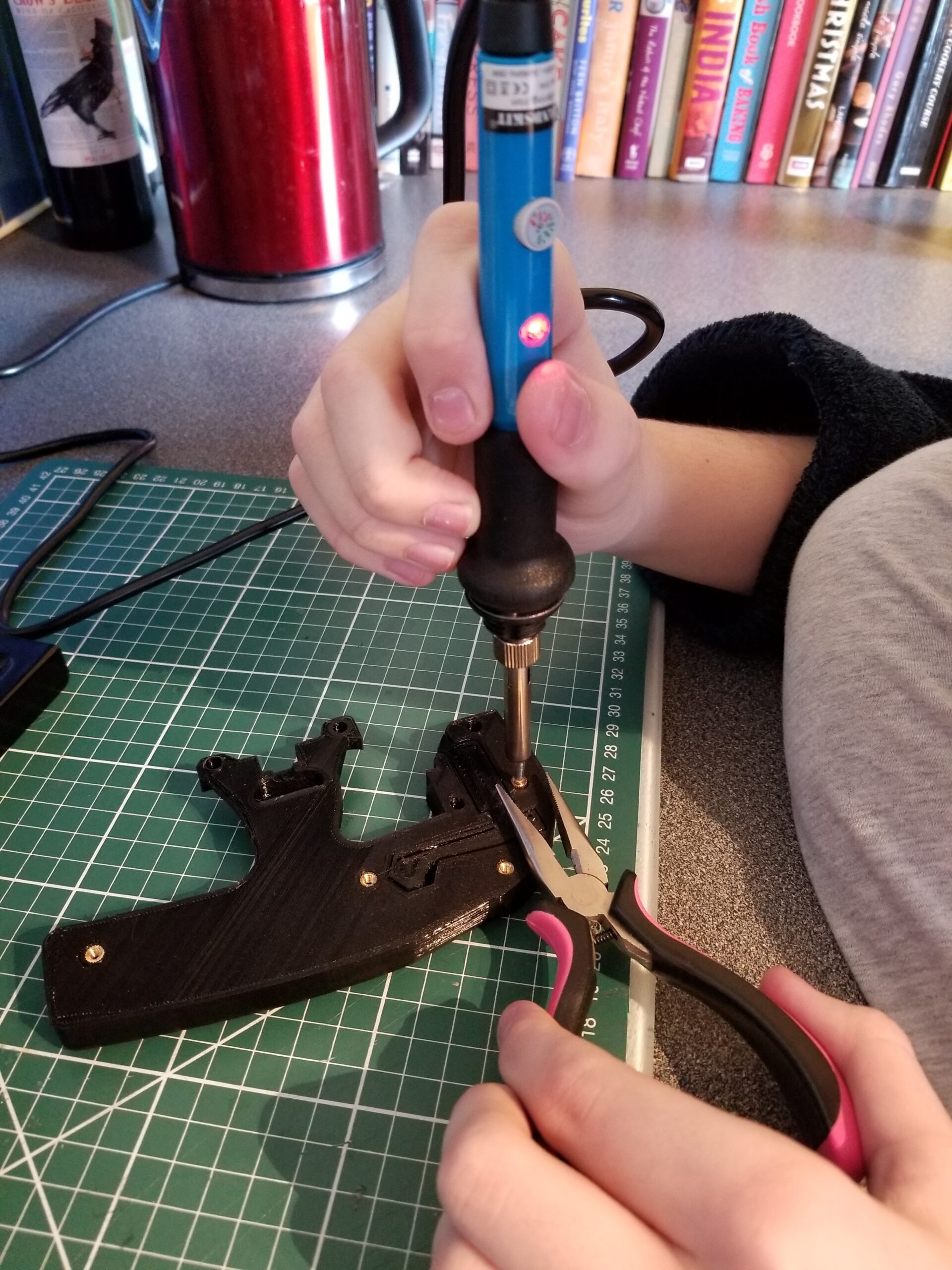
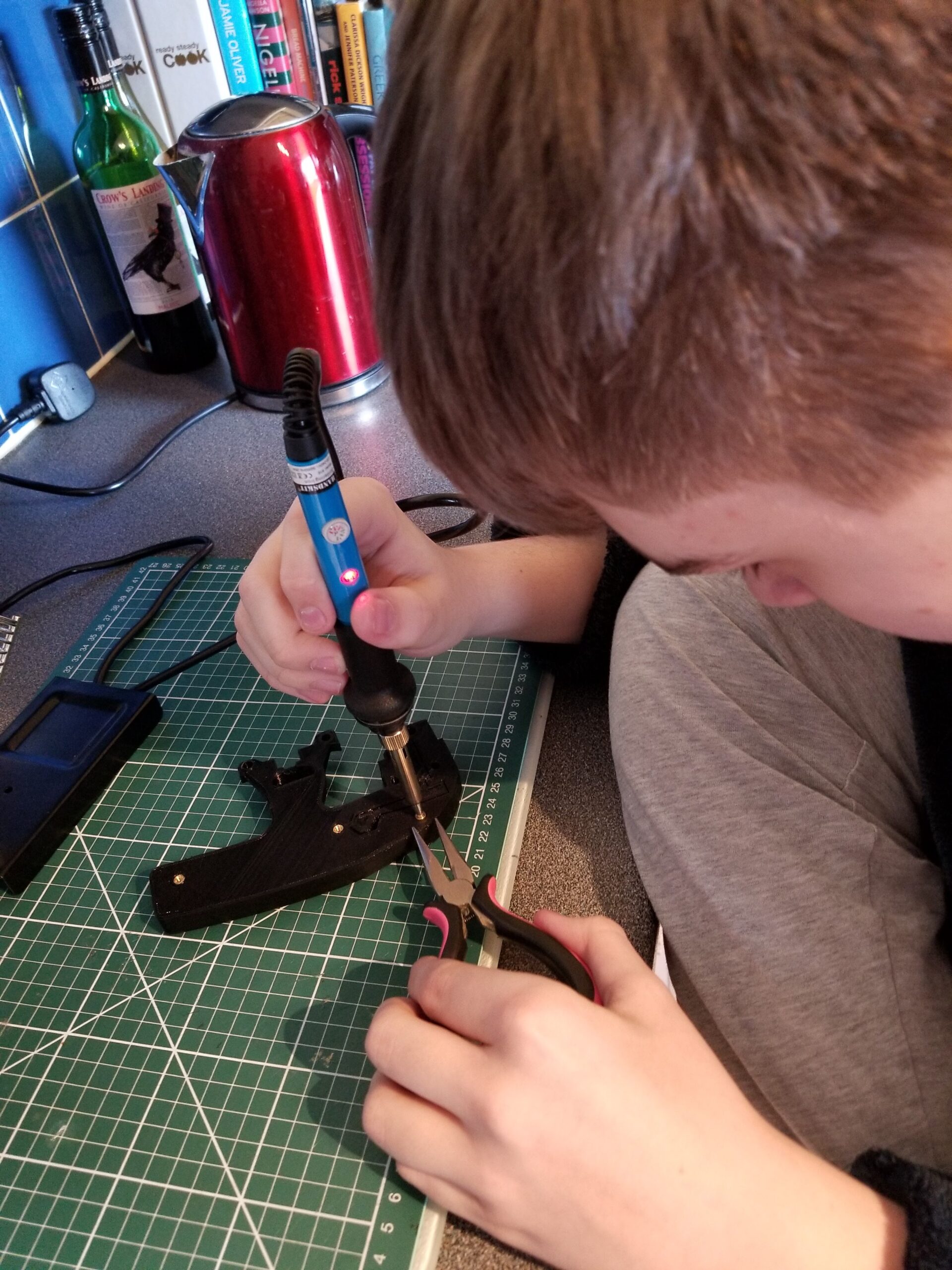
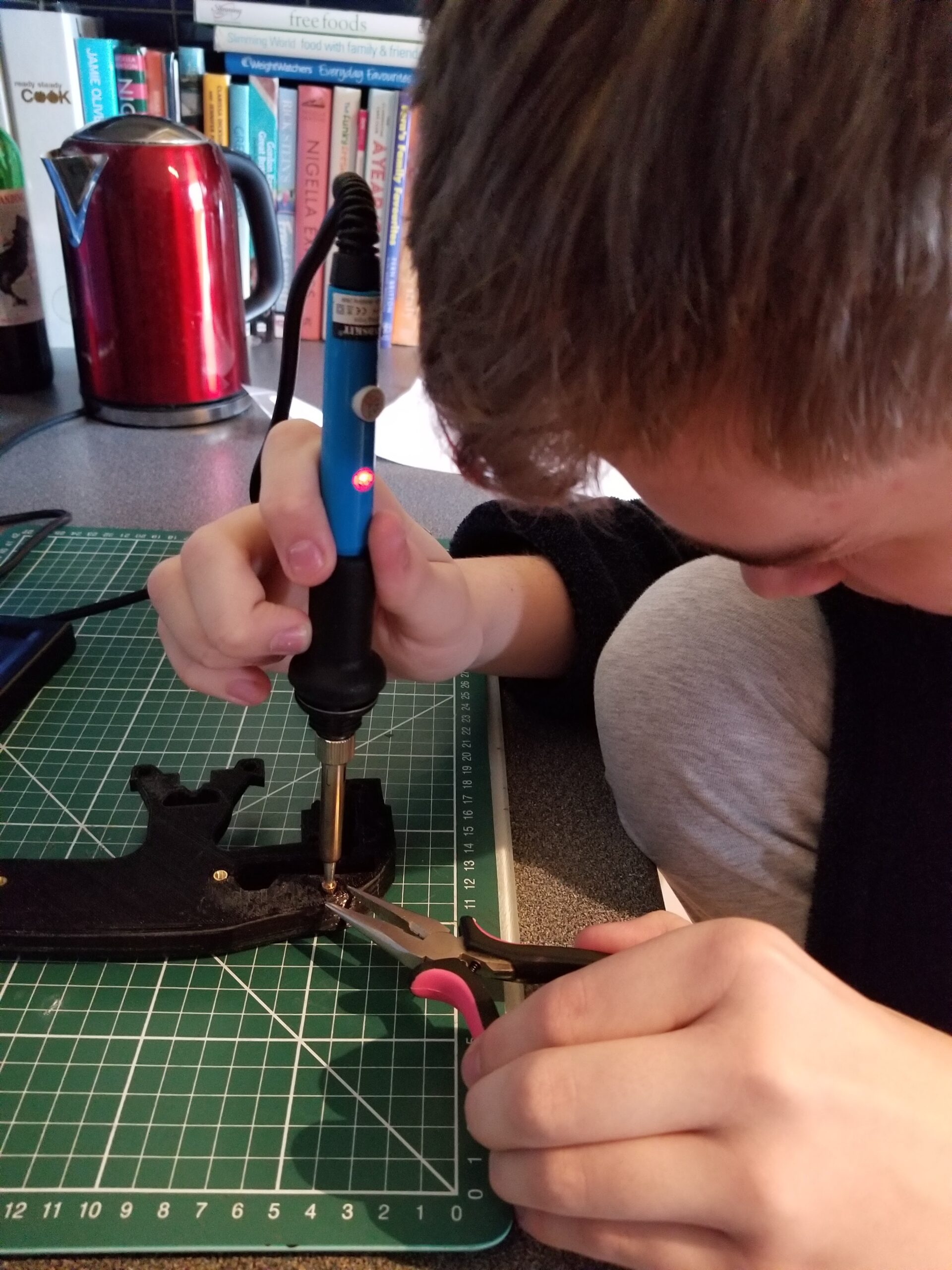
The first part of the rim I printed was the grips. After printing I used a soldering iron to melt in place the threaded inserts
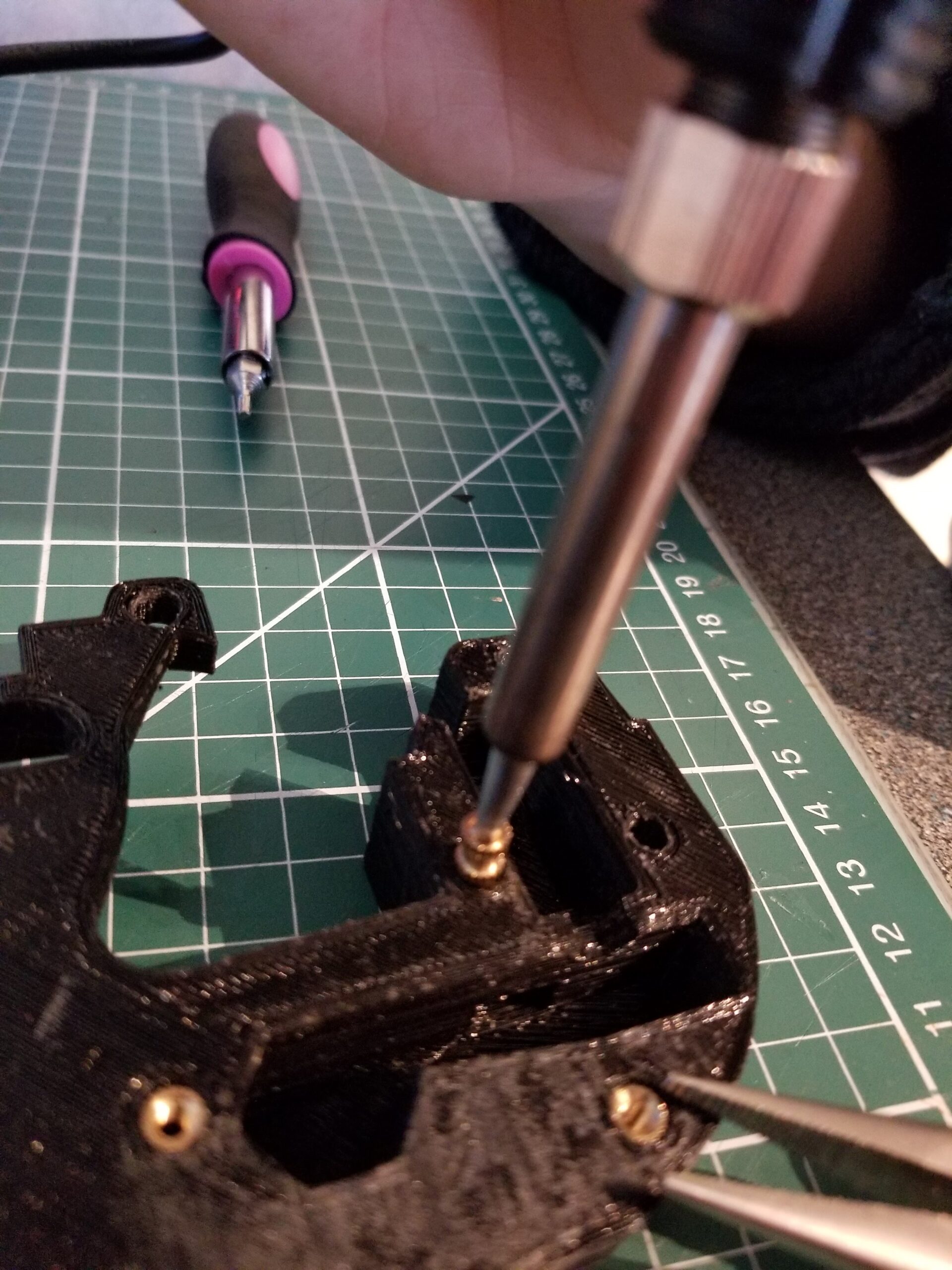
After all of the inserts were… inserted, it was time for the wiring and buttons.
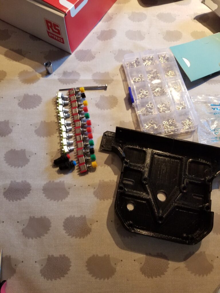
For the buttons and rotary encoders I used what was recommended in the original files.
To be able to actually use these inputs I used SimHub and an Arduino Uno, setting up a matrix for all of the switches. I initially tried to use a protoboard to make a little rats nest to simplify the process but it ended up complicating things even more.
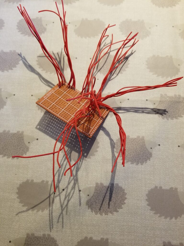
Instead I just daisy-chained all of the buttons together which was another rats nest but a slightly less confusing one.
After many hours on the soldering iron, melting a few button along the way, I finally finished it. And so, booted up Assetto Corsa to take this thing for a test drive.
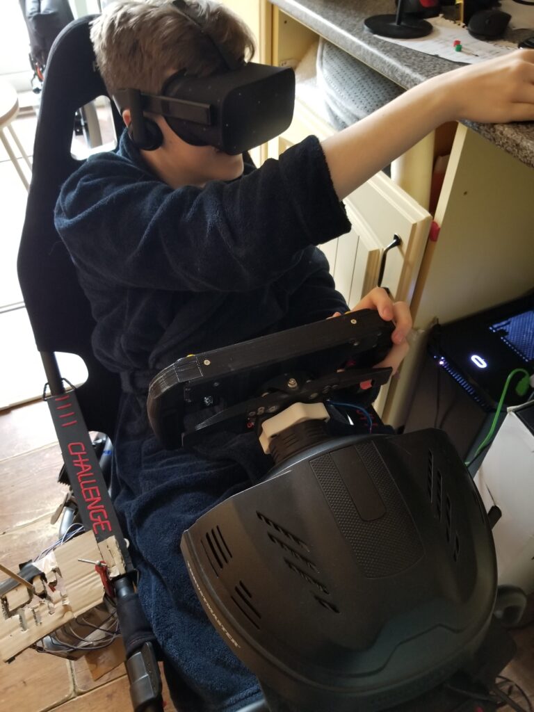
Unfortunately the test drive didn’t go so well as something, either the arduino or simhub, wasn’t really reliable and the lever arm shifter didn’t register gear changes most of the time.
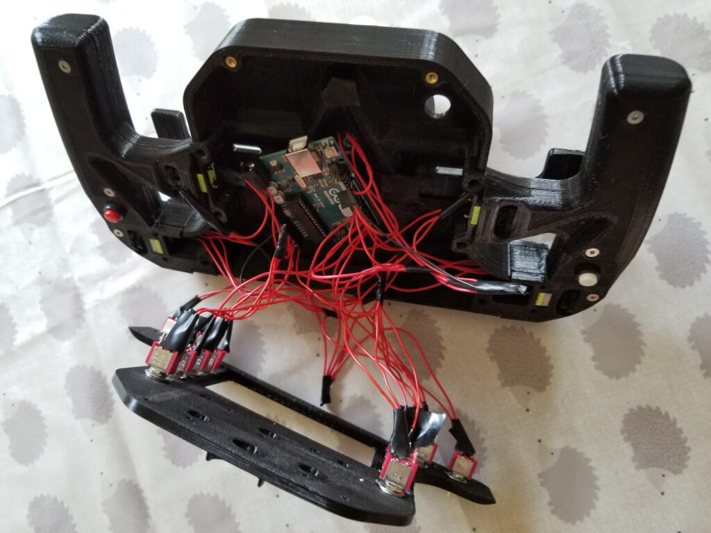
I decided to replace the interesting but non-operational paddle shifter with proper normal ones and to replace the arduino with a universal joystick encoder similar to one of these:
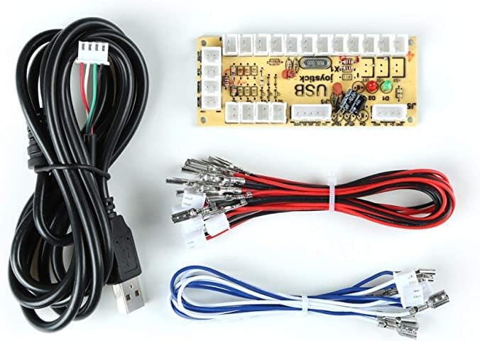
The proper paddle shifters feel way more tactile and despite the rotary encoder not being compatible with the joystick encoder, they didn’t even work in the first place as I melted them all! A similar fate was discovered for the original buttons is that I seemed to have used a soldering temperature way too high and so have melted all of those buttons too. In the end I replaced the original buttons with pre-soldered ones from amazon and used a new jst crimping kit to plug them into the joystick board.
This is the sad final state of the wheel today as I kind of lost interest as it seemed that there is always something not always working 100% of the time and one more thing stopping me from using it. I decided to move onto designing my own gear lever as throughout the project I had found a love for some of the older cars in PC2 and had started to want a H pattern shifter, maybe another post for the future,
Thanks for reading!