ANSWERED?Engine Design Regarding Stroke/Conrod Ratio and Off-Set Crankshaft, Now with Wrist Pin Offset: Desmos Illustration.

Recently I went to a university open day where I spoke to the Technical Specialist for Motorsport. There I showed him my previous blog on this topic and my questions in it regarding offset crank’s use in real life. He then explained that most of the time offset crank isn’t used as it makes packaging of the engine harder; I guess it also requires redesigning/building of the block during prototyping. He also explained that there is sometimes a small offset at the wrist pin instead to slightly achieve the same effect. The final problem he mentioned about offsetting anything is that it causes uneven wear to the cylinder wall, which makes sense.

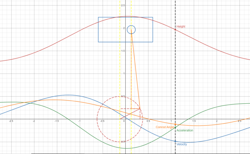
After getting home from the open day I created the graph below to see if offsetting the wrist pin does have the same effect as the crank offset in terms of connecting rod angle:

And as you can see, offsetting the piston has the same effect as offsetting the crankshaft! The problem that immediately came to thought is that this can increase frictional losses because the wristpin is no-longer in the centre of the piston, so the force from combustion (which is in the centre) is now creating a moment of torque around the wrist pin; causing the bottom right and top left sides of the piston to be pressed against the cylinder wall.

I tried to create a graph to show the torque mentioned above but had difficulty calculating the force from combustion:
While I think the force during compression seems pretty realistic (interpolating between 1*atmosphere and compression ratio*atmospheric pressure), the pressure during combustion has to be off. I’m certain the cylinder cannot have approximately 100GPa at the beginning of combustion, right? (my working out is below)
I used the formula PV = k modified to PV = E as the SI units multiply to form Joules and then found E using the chemical energy density of gasoline and an air fuel ratio of 14.7 to 1 (assuming volumetric efficiency of 100%). I think the inaccuracies are caused by not modelling the thermal losses of the cylinder, which normally takes away from the energy used from combustion.

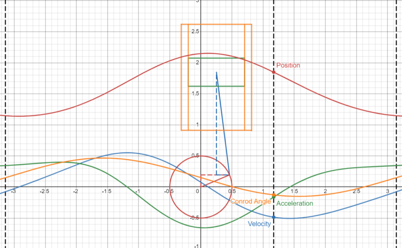
After the confusing failure of the forces graph I decided to see what would happen if I decide to mix the wrist pin and crank shaft offsets together and therefore made this graph:

As expected, the normal reduction of connecting rod angle occurred but I’m still curious as to what forces are being put into the cylinder walls; maybe next time, potentially using an engine simulator to get a plot of the pressure vs crank angle!

Thanks for Reading!

Engine Design Regarding Stroke/Conrod Ratio and Off-Set Crankshaft: Desmos Illustration

Recently I have been watching a few videos by Driving4Answers on different engine layouts and why they exist mostly based on primary and secondary reactive forces from the piston and connecting rod moving during normal operations. While binge-watching these videos of his I came across a video explaining the importance of the stroke/conrod length ratio and it’s impacts on the acceleration of the piston(s).

He explained that as the conrod is pulled to the side by the crankshaft it must decrease in overall height to maintain a constant length, therefore pulling the piston down quicker.

After watching the video a few times I decided to make a graphical representation of the effect of this ratio using the Desmos Graphing Calculator

First Iteration

The first iteration of this graph was pretty simplistic, it only showed the moving piston and crankshaft with a list of variables to change. When the stroke is much larger than the conrod you can kind-of tell that the piston stays at the bottom for longer but too much and it glitches out, needless to say I had to go further:

Second Iteration

To make it easier to see the changes in the acceleration from using different ratios I created a second graph that also plots the position, velocity, acceleration, jerk and snap of the piston and also the angle of the connecting rod for some reason.

Experimenting with Iteration 2

Using iteration 2 I was able to easily compare different ratios to see their effect on: how even the position, velocity and acceleration of the piston is.

Conrod Length = Stroke:

When the conrod is the same size as the stroke the piston seems to stay at the bottom for longer than it does the top.

Conrod Length > Stroke:

When the conrod is longer than the stroke (50% this case) the piston seems to spend more of an equal amount of time at either end of the stroke.

Conrod Length < Stroke:

When the conrod is smaller than the stroke (50% this case) the piston is at a stand-still for most of the rotation until the crankshaft is above axis of it’s rotation. I would say that this mechanism with these dimensions would be impossible in real life.

Conrod Length approx infinity:

Although the length technically becomes undefined, the acceleration and velocity (and presumably position) become perfectly sinusoidal as the conrod is infinitely more times larger than the stroke radius.

Crankshaft Off-Set

With the second graph I found it much easier to spot the effect and so I left the idea alone for a while until I saw another one of d4a’s videos.
In this new video he showed the effect of off-setting the crankshaft from the cylinders to reduce the maximum angle of the connecting rod during the power stroke to reduce frictional losses.

First Iteration

I decided that this was also interesting and therefore decided to re-make my second graph into one that could also move the cylinders laterally.
In the first iteration of the off-set-able graph I simply altered the second graph by adding an off-set in certain places. Through experimentation I found that setting the off-set to a quarter of the stroke reduces the maximum and average angle of the connecting rod during the power-stroke, I later set this as the default value for the off-set.

Second Iteration

After a while of fiddling with my new graph I thought it would be cool to be able to see multiple pistons at the same time and potentially have them angled. The way I was illustrating the piston was that I was creating a table of points and telling Desmos to draw lines between them; unfortunately Desmos won’t let you input a table into another so I couldn’t just make a table of values for each piston and have another table render each one so I had to make my own way to draw lines between points.

This was just a simple function to take in 2 sets of coordinates and create a line between them.

But to allow for cylinder angle I had to add an angle to the drawLine otherwise I’d have to constantly work out a new angled point.

It took a lot of thinking and evil math but I got it working.

And so finally I created the graph to allow for cylinder angle and multiple pistons, I also added cylinder walls too!

I decided to make the default values that of the Harley Davidson Milwaukee 8 Big Twin.

My Question:

My one question about off-setting the crankshaft is are there any engine manufacturers actually doing this in their engines as I haven’t found an example of one yet?

Thanks for reading!

No comments to show.